ADAPT Prototype
2026
From concept to something you can actually touch.
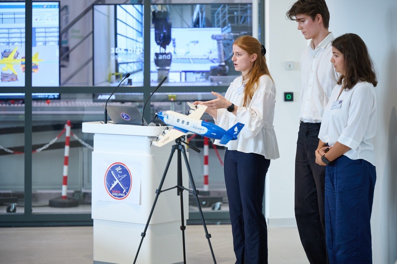
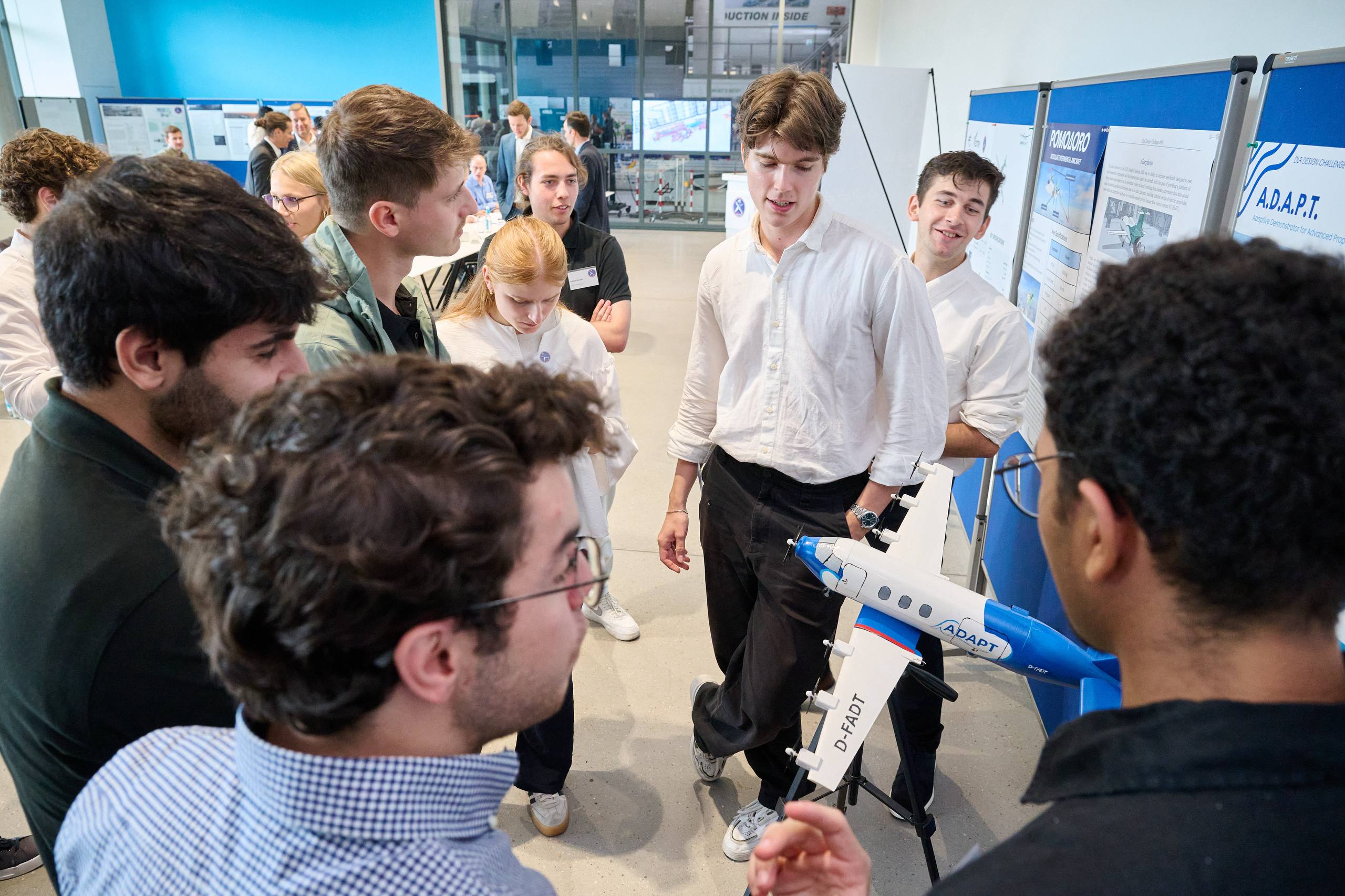
By the end of the DLR Design Challenge, ADAPT existed as a fully digital aircraft. For the final presentation, we wanted to take one part of it a step further and turn the design into a physical demonstrator.
A fully flying model was never realistic within the roughly two weeks we had left. A completely static one, however, would have missed one of the central ideas behind ADAPT: modularity.
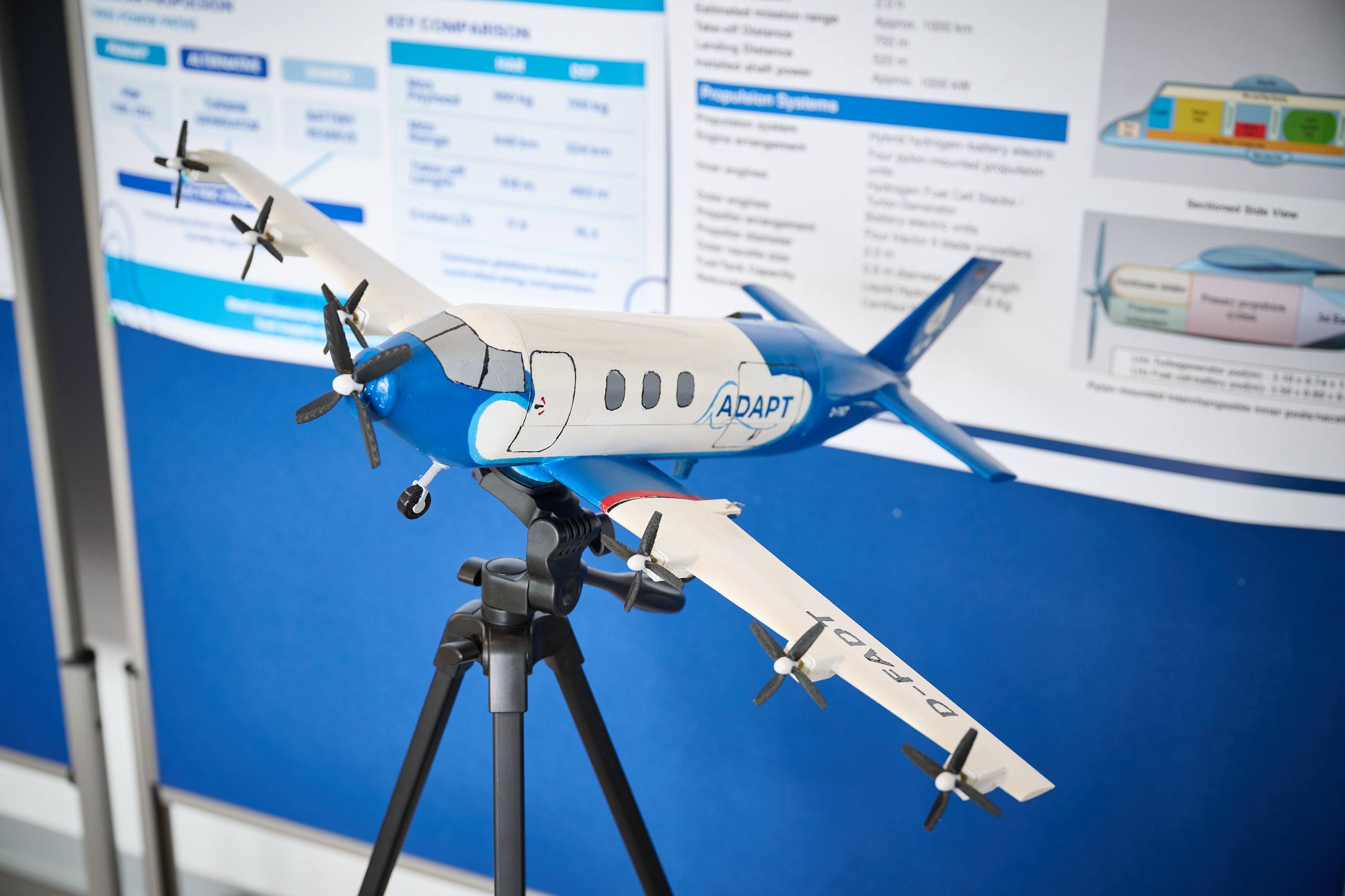
So the goal became a scale demonstrator with interchangeable wing configurations and working electric propellers.
1:25, because printers have limits.
The scale was mostly decided by three things: the build volume of the available 3D printer, enough internal space for real electronic components and the need for the aircraft to remain clearly visible during the presentation.
At 1:25, the model was just small enough to manufacture while still leaving room for the battery, motors and mechanical interfaces inside.
The bigger constraint was time. From the first CAD adjustments to the finished aircraft, the entire demonstrator had to come together in roughly two weeks while we were all still working full-time jobs.
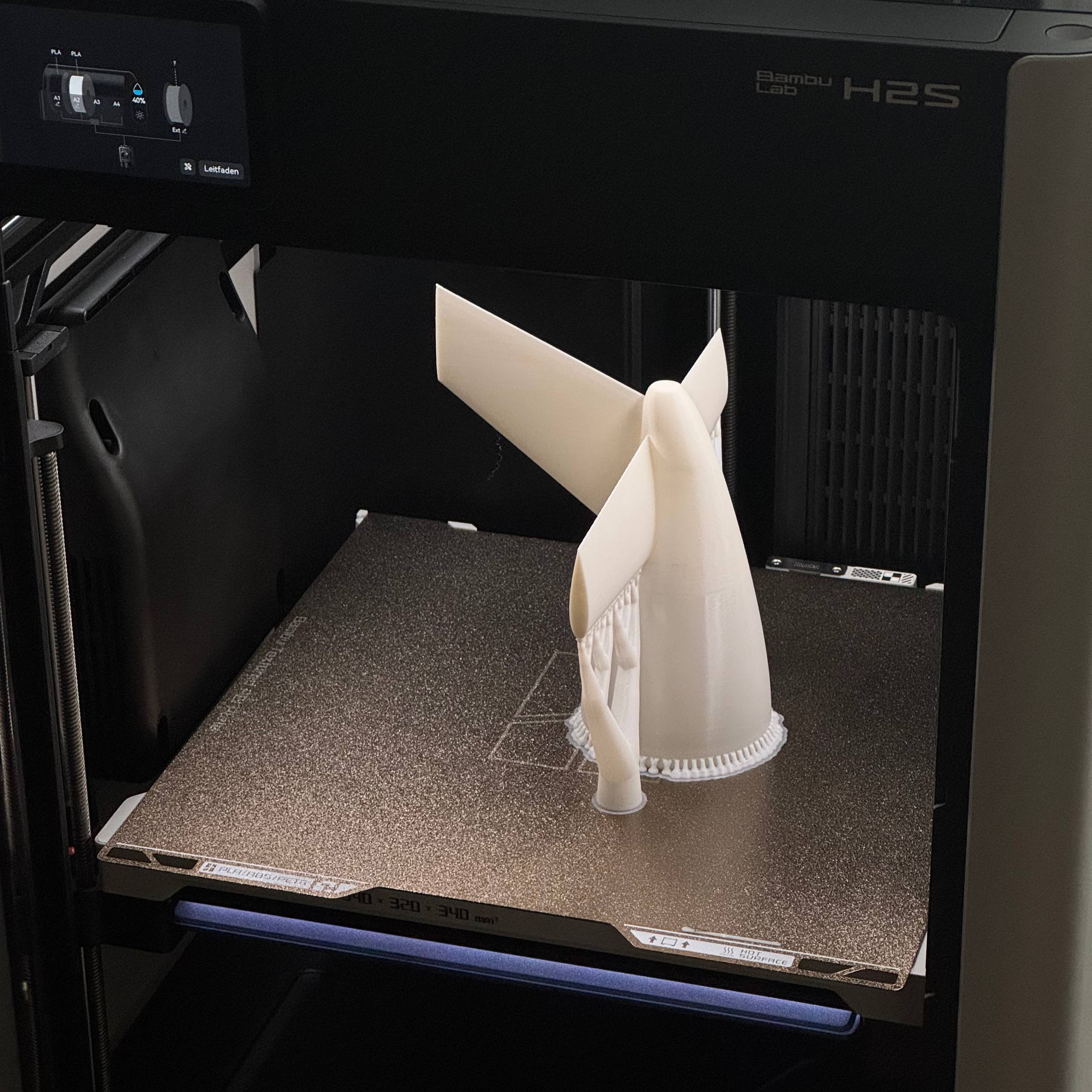
From aircraft geometry to printable parts.
The starting point was the OpenVSP geometry used for the final ADAPT configuration. It looked like an aircraft, but that did not mean it was ready to come out of a printer.
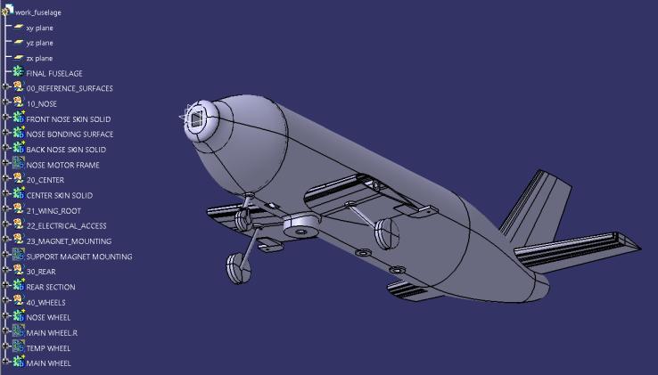
The geometry first had to be turned into printable solid bodies and then split into sections small enough for the available build volume. From there, the CAD work became less about reproducing the digital aircraft and more about figuring out how the physical one would actually go together.
The fuselage sections received locating and bonding features, the wing root was redesigned around a beechwood spar and components such as the landing gear and propellers had to be modeled specifically for the demonstrator.
Making modularity actually modular.
The whole point of the prototype was that the wing configuration could be changed.
Both the high aspect ratio (HAR) wing and the distributed electric propulsion (DEP) wing therefore used the same mechanical interface. A wooden spar passed through the fuselage to carry the wings, while an additional locking feature prevented them from rotating or sliding back out.
It was not the prettiest mechanism ever hidden inside an aircraft. It did, however, survive assembly, transport and repeated wing changes, which was considerably more useful.
Seven tiny motors later.
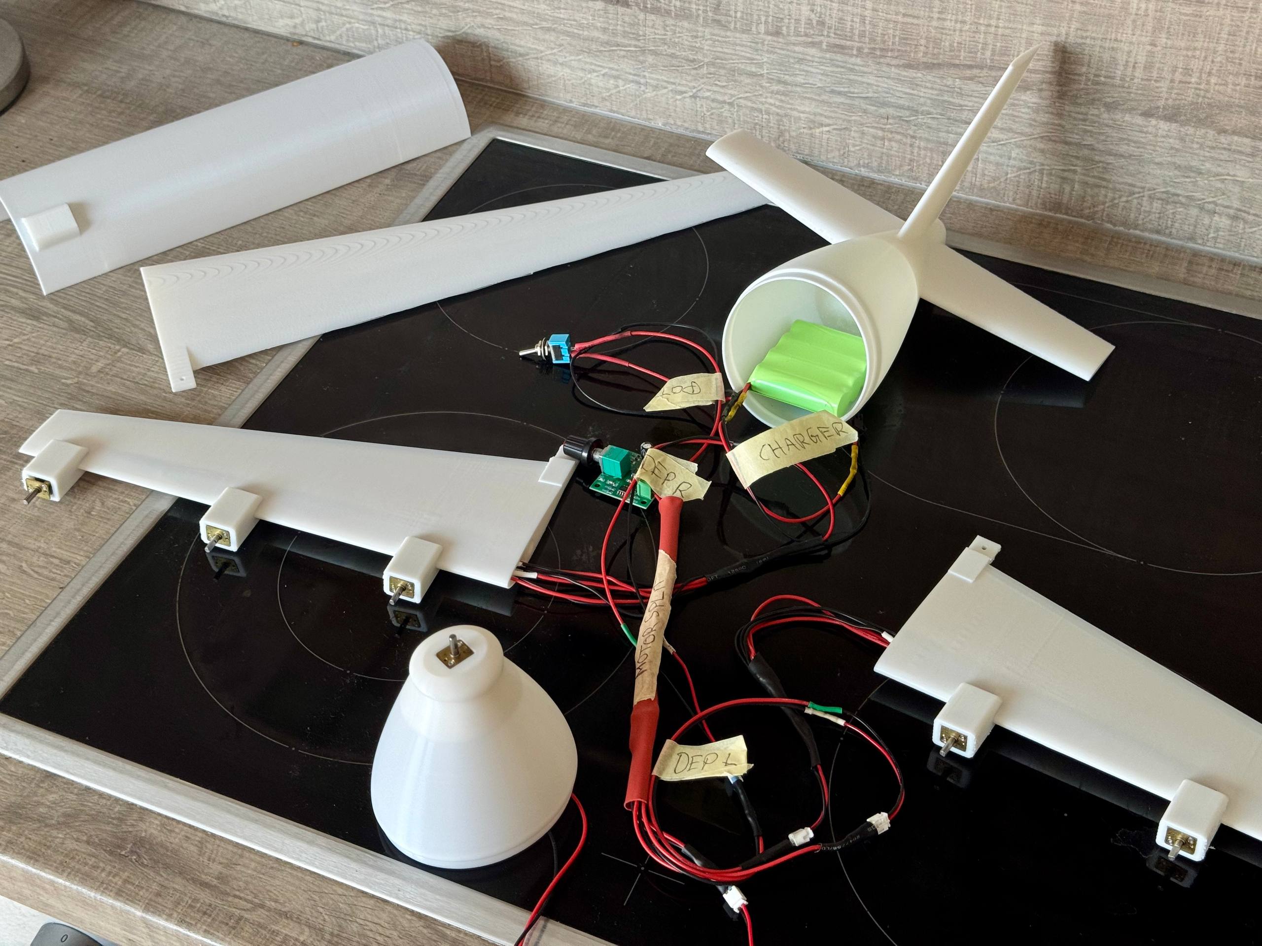
The DEP configuration needed more than a visual representation. Its propellers were supposed to actually spin.
The demonstrator therefore received a simple electrical system built around a 2400 mAh battery, seven small DC motors, a controller and a switch. The components were wired together and the connections soldered by hand before everything was integrated into the aircraft. The wiring ran through the fuselage and into the interchangeable DEP wings, allowing all of the propellers to operate during the presentation.
That created another problem: once everything was assembled, the electronics still needed to be accessible.
The center fuselage was therefore split into a fixed lower shell and a removable upper shell held in place by magnets. The battery, controller, wiring, switch and charging connection could all remain hidden inside the aircraft without becoming permanently trapped there.
Sand. Paint. Repeat.
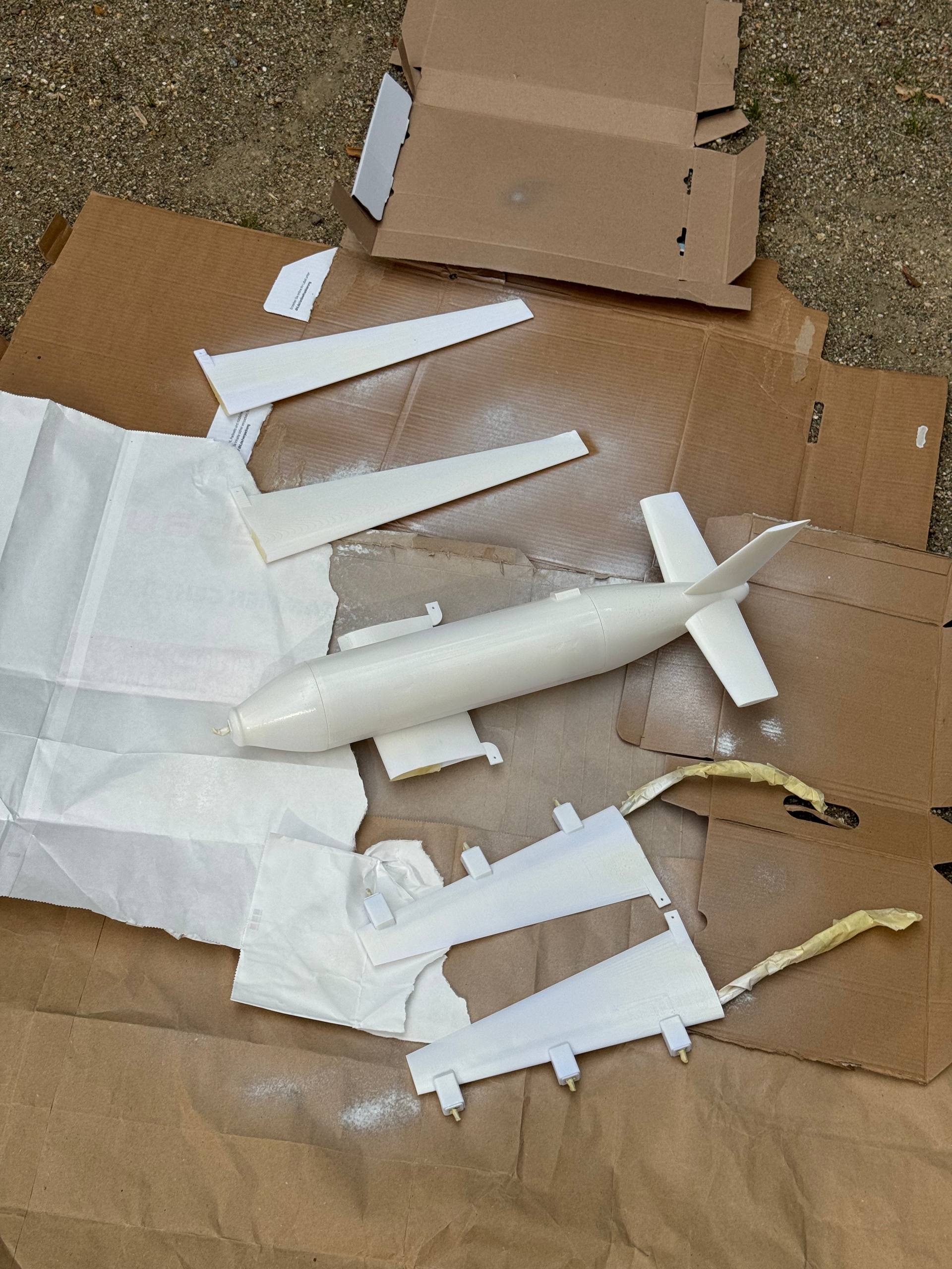
Once the parts were printed and the aircraft worked mechanically and electrically, it still looked very much like a collection of 3D-printed parts.
Everything was sanded, covered in a white primer coat and masked for the two blue color tones of the final ADAPT design. Smaller details were added afterward before several layers of clear coat sealed the surface.
Final assembly complete.
Two weeks after starting with the digital aircraft geometry, ADAPT existed as a physical 1:25 demonstrator.
Both wing configurations could be installed on the same fuselage, the DEP and nose propellers were electrically driven and the internal electronics remained accessible through the removable fuselage section.
Not quite a flying aircraft, but a functional physical version of the concept we had spent the previous months developing digitally.
Toolkit
- Software
- CATIA V5 · Bambu Studio
- Engineering Methods
- 3D Printing · Prototype Assembly · Wiring · Surface Finishing
Media Gallery